Fluid Dynamics Fundamentals
Master the core fluid-mechanics principles that explain how a hovercraft achieves lift and forward thrust through pressurized air.
📖 Overview
Master the core fluid-mechanics principles that explain how a hovercraft achieves lift and forward thrust through pressurized air.
📚 Study Guide
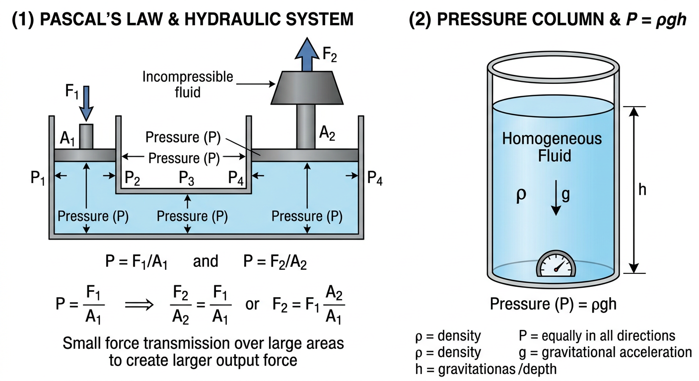
2.1 Pressure & Pascal's Law
Pressure: Force per Unit Area
Pressure is defined as force distributed over an area:
P = F / A
Where:
- P = pressure (Pa, or N/m²)
- F = force (N)
- A = area (m²)
This simple formula has profound implications for hovercraft design. A given force can produce very different pressures depending on the area it acts over:
- A 10 N force distributed over 1 m² produces 10 Pa of pressure
- The same 10 N force concentrated on 0.01 m² produces 1000 Pa of pressure
In a hovercraft, the lift fan does work (applies force) to accelerate air. That air is then trapped under the vehicle's skirt, creating pressure inside the cushion. If the trapped air fills a large cushion area (say, 0.13 m²), the pressure is lower. If the same amount of air is trapped in a small area (say, 0.05 m²), the pressure is higher. This relationship is fundamental to skirt and base design.
Pascal's Law: Pressure Transmits Equally
Pascal's Law states:
"A pressure applied to an enclosed fluid is transmitted equally in all directions throughout the fluid."
In practical terms: If you have a sealed container filled with air or liquid, and you apply pressure at one point, that pressure spreads throughout the container. Every point in the fluid experiences the same pressure increase.
For a hovercraft, this principle is critical. The lift fan pumps air into a sealed cushion (created by the skirt and the vehicle base). The pressure inside the cushion is approximately uniform—not higher at the fan inlet and lower at the skirt edge, but roughly the same everywhere.
This uniform pressure acts perpendicular to every surface it contacts:
- On the base (above): Pressure pushes upward
- On the ground (below): Pressure pushes downward
- On the skirt (sideways): Pressure pushes outward, which tensioning the skirt material and contributing to stability
The upward pressure force on the base is what lifts the vehicle:
F_lift = P_cushion × A_cushion
I
…
2.2 Bernoulli's Principle
The Core Principle
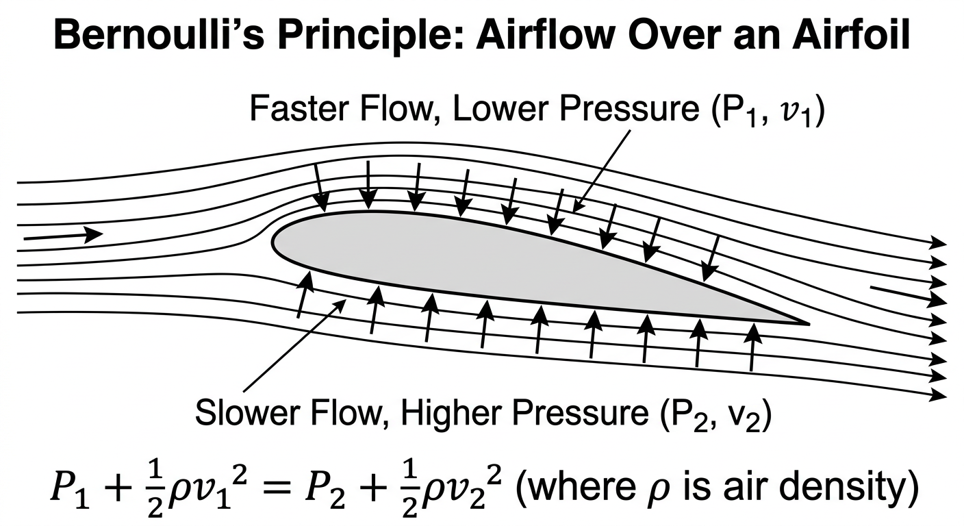
Bernoulli's Principle states that within a flowing fluid, faster-moving fluid has lower pressure than slower-moving fluid. Mathematically:
P + ½ρv² + ρgh = constant
Where:
- P = static pressure (Pa)
- ρ = fluid density (kg/m³)
- v = fluid velocity (m/s)
- g = gravitational acceleration (9.81 m/s²)
- h = height (m)
For a horizontal flow at constant altitude (h = 0), this simplifies to:
P + ½ρv² = constant
The takeaway: if velocity increases, static pressure must decrease to keep the sum constant.
This principle is counterintuitive. Most people assume that faster-moving water or air has higher pressure, but the opposite is true. This effect is crucial for hovercraft propulsion and lift systems.
Why Bernoulli Matters for Hovercrafts
In the lift fan:
- Air at the fan intake is slow-moving and at atmospheric pressure
- The impeller blades accelerate the air to high velocity
- As the air velocity increases, its static pressure drops (Bernoulli effect)
- At the fan outlet, the air is moving fast but at relatively low pressure
- This air is directed under the skirt, where it slows down (due to the confined space and the skirt edge), causing pressure to increase again
- The pressure builds up inside the cushion, creating lift
In the thrust propeller:
- The propeller accelerates air backward (relative to the vehicle)
- Fast-moving air behind the vehicle has lower pressure
- Atmospheric pressure ahead of the vehicle is higher
- The pressure difference pushes the vehicle forward
- This is the fundamental mechanism of thrust generation
The Continuity Equation and Bernoulli
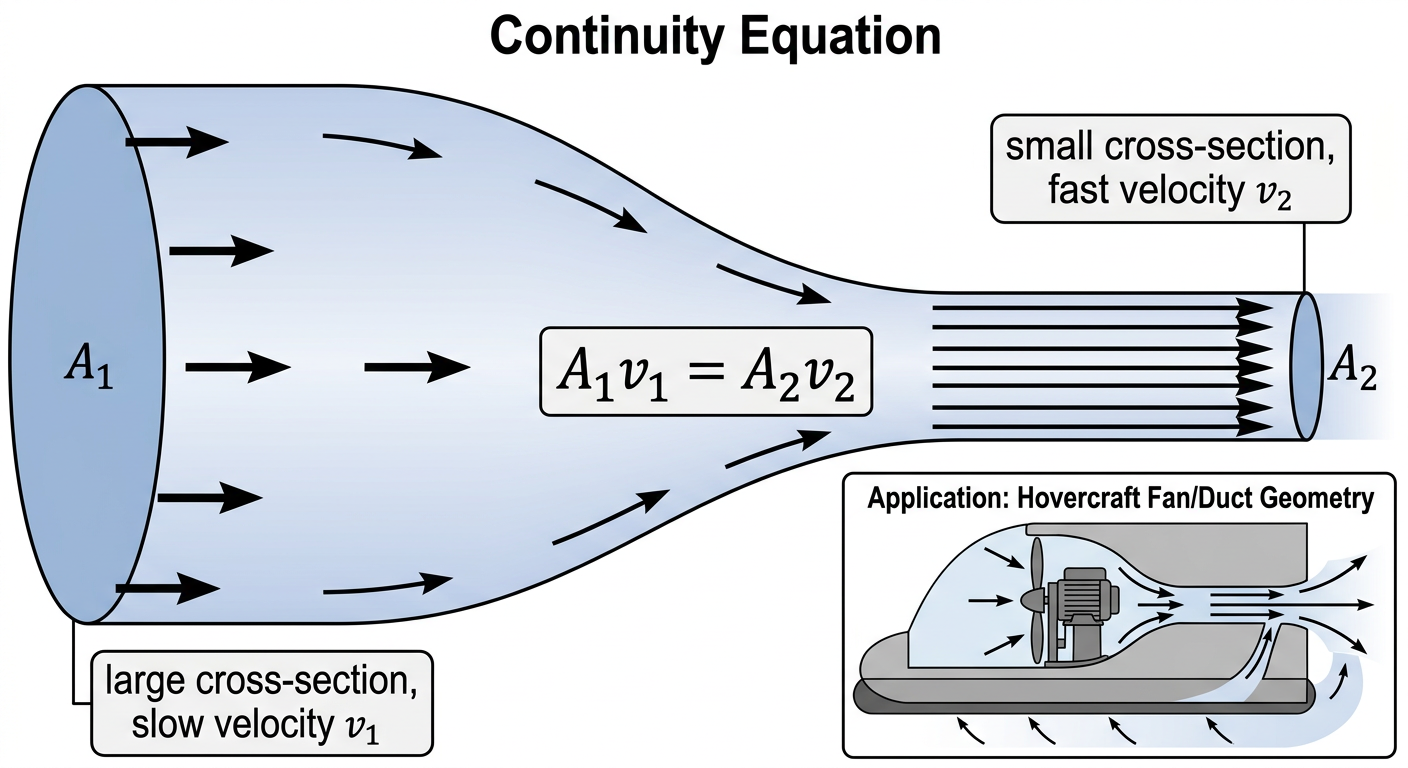
The continuity equation (covered in detail in Topic 2.4) states that for incompressible flow in a pipe or duct:
A₁v₁ = A₂v₂
Combining continuity and Bernoulli:
- If a duct narrows (area decreases), velocity must increase (continuity)
- If velocity increases, pressure must decrease (Bernoulli)
- This is why wind a
2.3 Air Cushion Dynamics
The Air Cushion Concept
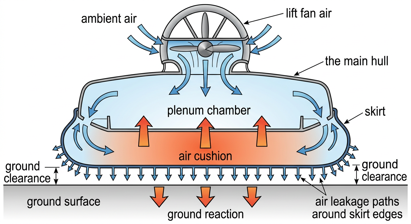
A hovercraft creates lift by pumping pressurized air under a flexible skirt, creating a thin layer of high-pressure air between the vehicle base and the ground. This air cushion supports the vehicle's weight and allows it to "float" a few centimeters above the surface with almost no physical contact.
The air cushion is not a sealed bubble. Air continuously flows in from the lift fan and escapes from gaps around the skirt edge (and from designed perimeter holes). The system reaches equilibrium when inflow equals outflow, and the pressure inside stabilizes at a value that supports the vehicle.
The Equilibrium Condition
At equilibrium:
Flow Rate In = Flow Rate Out
Or more explicitly:
Q_fan = Q_leak
Where:
- Q_fan = volume flow rate from the lift fan (m³/s)
- Q_leak = volume flow rate escaping from the skirt perimeter (m³/s)
This balance determines the pressure inside the cushion. Here is why:
- If the fan pushes more air than can escape, pressure builds until the increased pressure gradient overcomes friction and expels air faster, restoring balance.
- If air escapes faster than the fan can replenish it, pressure drops, and the vehicle sinks until the skirt is compressed enough to restrict outflow, restoring balance.
The system self-regulates through this mechanism.
Pressure Inside the Cushion
The equilibrium pressure depends on:
-
Fan output (Q_fan and P_fan): A more powerful fan produces more flow and higher pressure.
-
Skirt seal quality: A well-sealed skirt minimizes leakage and allows higher pressure to build. A leaky skirt bleeds air away, limiting pressure.
-
Skirt geometry: The shape and size of the cushion area determine how easily pressure distributes.
-
Perimeter escape hole design: Most hovercraft have small holes around the skirt perimeter designed to release excess air in a controlled manner. These holes regulate pressure by providing a predic
2.4 Continuity Equation & Mass Flow Rate
The Continuity Equation
The continuity equation is a cornerstone of fluid mechanics. It states that mass is conserved in a flowing fluid. For a fluid flowing through a pipe or duct with no branching:
ṁ = ρ × A × v = constant
Where:
- ṁ = mass flow rate (kg/s)
- ρ = fluid density (kg/m³)
- A = cross-sectional area (m²)
- v = velocity (m/s)
In words: The mass of fluid entering a section of pipe per unit time must equal the mass leaving per unit time. The mass does not accumulate or disappear.
For incompressible flows (like liquids, or for air at low speeds), density is constant, so the equation simplifies to:
Q = A × v = constant
Where Q is the volume flow rate (m³/s).
This simplified form is often called the incompressible continuity equation and is the one most relevant to hovercraft design.
Understanding the Relationship
Continuity leads to an important insight:
If the cross-sectional area increases, velocity must decrease (to conserve flow). If the area decreases, velocity must increase.
Example: A duct carries air at 10 m/s through a 0.01 m² cross-section, giving a flow rate:
Q = 0.01 m² × 10 m/s = 0.1 m³/s
If the duct narrows to 0.005 m², to conserve flow rate:
0.1 m³/s = 0.005 m² × v_new v_new = 20 m/s
The air doubles in speed when the area halves. This velocity increase directly impacts pressure through Bernoulli's principle (faster air = lower pressure).
Continuity in Hovercraft Systems
Lift fan inlet and outlet:
A typical small centrifugal lift fan has:
- Inlet diameter: 2–3 cm
- Outlet diameter: 3–4 cm
The air accelerates from the inlet to the impeller (where velocity is highest) and then decelerates in the diffuser before reaching the outlet. The cross-sectional areas determine the velocity profile:
- At the inlet (large area), air velocity is moderate
- At the impeller exit (smallest area in the fan), air velocity is maximum
- At the outlet (larger ar
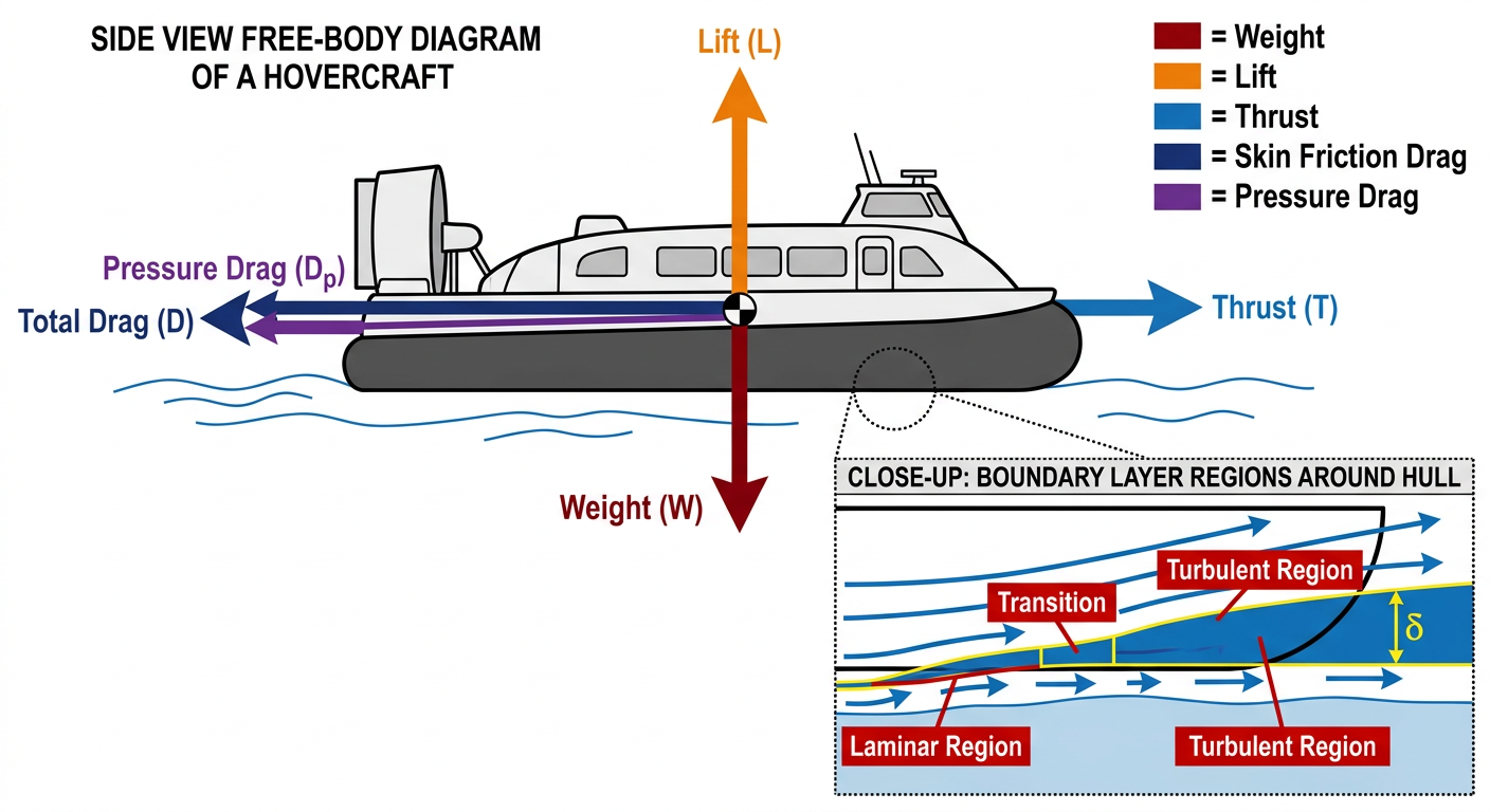
2.5 Drag & Friction Forces
The Two Main Resistance Forces
A hovercraft in motion encounters two primary resistive forces that slow it down and limit distance:
-
Friction between the skirt and the ground — The skirt material touches or hovers just above the track surface, experiencing friction as the vehicle moves.
-
Aerodynamic drag on the body and fins — Air resistance acts on the vehicle's hull and any protruding components.
Both forces remove kinetic energy from the vehicle, converting it to heat and sound. Minimizing these forces is essential for maximizing distance and speed.
Skirt-Ground Friction
Friction force is given by:
F_friction = μ × N
Where:
- μ = coefficient of friction between skirt material and track surface
- N = normal force (the force pressing the skirt into the ground)
For a hovering hovercraft, the normal force N is approximately the vehicle's weight (m·g), because the vehicle is supported by air pressure from below and gravity pulls from above. At hover equilibrium, these nearly balance, so:
N ≈ m · g
Therefore:
F_friction ≈ μ × m × g
Notable points:
-
Heavier vehicles experience more friction. A 500 g vehicle experiences 1.67× more friction than a 300 g vehicle (all else equal). This is one reason why mass matters enormously in hovercraft design.
-
Friction depends critically on surface and skirt material. A smooth linoleum floor (μ ≈ 0.05–0.08) produces much less friction than rough concrete (μ ≈ 0.15–0.25) or carpet (μ ≈ 0.30+).
-
Friction is independent of velocity (for typical hovercraft speeds). The friction force is roughly constant whether the vehicle is moving at 0.5 m/s or 3 m/s. (This is kinetic friction, as opposed to static friction, which governs whether something starts moving.)
Impact of Friction on Distance
Assuming the propeller produces constant thrust F_thrust, the vehicle's acceleration is:
**a = (F_thrust - F_friction) / m = (F_thrust - μ × m × g) / m
…
2.6 Viscosity & Boundary Layer Basics
Viscosity: Fluid Resistance to Motion
Viscosity is the property of a fluid that describes its resistance to shear stress—its internal friction. It quantifies how "thick" or "sticky" a fluid is.
Dynamic viscosity is denoted μ_dyn (not to be confused with coefficient of friction μ, which is different) and is measured in Pa·s (pascal-seconds) or poise.
Examples:
- Water at 20°C: μ_dyn ≈ 0.001 Pa·s ("low viscosity," flows freely)
- Honey at 20°C: μ_dyn ≈ 10 Pa·s ("high viscosity," flows slowly)
- Air at 20°C: μ_dyn ≈ 0.000018 Pa·s (extremely low viscosity; air is much less viscous than water)
For fluid flow in a pipe, the shear stress at the wall is related to viscosity and the velocity gradient:
τ = μ_dyn × (dv/dy)
Where dv/dy is the rate of change of velocity perpendicular to the flow direction. Near the wall, this gradient is steep (velocity drops from moving fluid to zero at the wall), so shear stress is high.
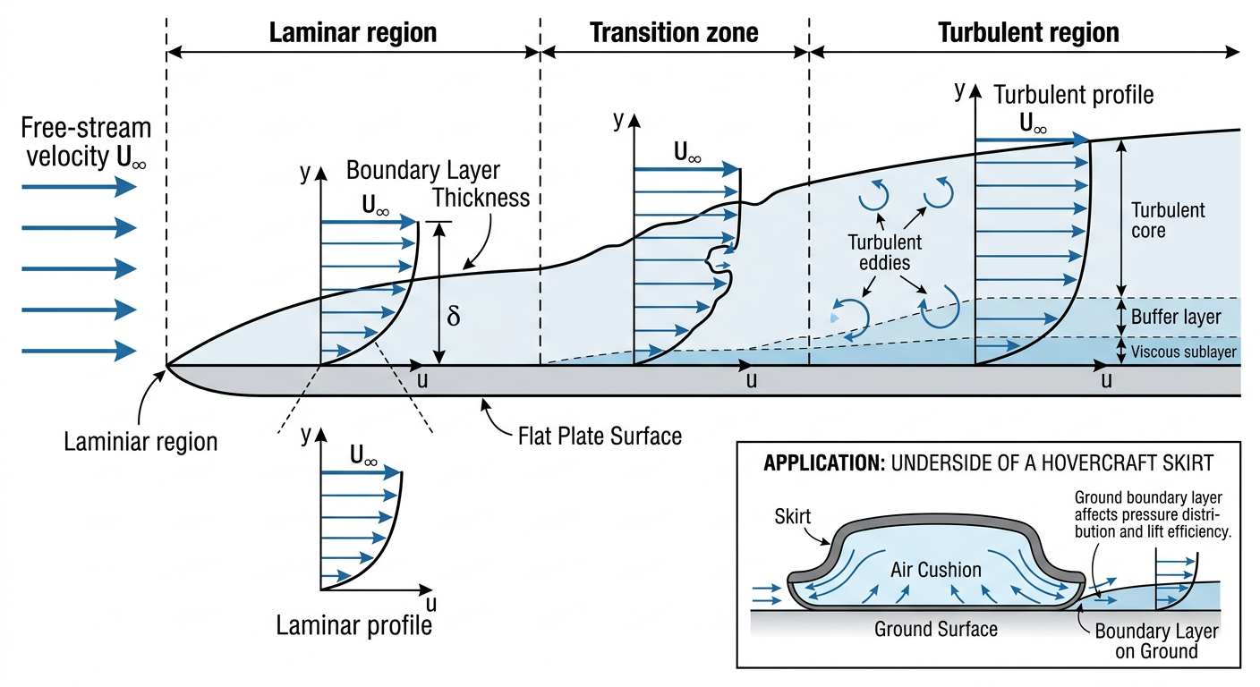
For a hovercraft, air viscosity is low, so its effects are often overlooked. However, at the boundary between the air flow and solid surfaces (skirt, body, ground), viscosity becomes important, creating the boundary layer.
The Boundary Layer
The boundary layer is a thin region of fluid near a surface where viscous forces are significant. Outside the boundary layer, the fluid flows freely without much influence from the surface. Inside the boundary layer, friction with the surface slows the fluid down.
Boundary layer thickness (δ) grows as fluid flows downstream along a surface and is typically proportional to:
δ ≈ √(μ × L / (ρ × v))
Where:
- μ = dynamic viscosity
- L = distance along the surface from the leading edge
- ρ = fluid density
- v = free-stream velocity
For air flowing at 2 m/s over a 0.3 m long surface (like a hovercraft base):
δ ≈ √(0.000018 × 0.3 / (1.2 × 2)) ≈ √(0.00000225) ≈ 0.0015 m ≈ 1.5 mm
The boundary layer for a hovercraft body is quite thin—a few milli
…
❓ Practice Questions
No practice questions linked to this module yet.
🎬 Study Videos
🔗 Resources
-
Official Science Olympiad event page for Hovercraft (Division C). Contains event description, links to official rules, recommended resources, and preparation guidance.
-
Full 2026 Hovercraft event rules including scoring formulas (TS, DS, BS), construction and competition violation penalties, tiebreaker criteria, and prohibited components.
-
Foundational curriculum guide explaining what a hovercraft is and the physics of air cushion lift. Free educational material from the international school hovercraft project — ideal for Module 2 grounding.
-
Explains how increasing air pressure under the hovercraft skirt generates the lift force that raises the vehicle off the ground. Covers the relationship between fan air volume and cushion pressure.
-
Quantitative treatment of hovercraft lift: lift force = cushion pressure × skirt enclosed area. Includes formulas for air gap clearance and pressure calculations relevant to Module 2 physics.
-
NASA's Beginner's Guide to Aeronautics covering all three of Newton's Laws with applications to thrust and drag. Essential physics background for understanding hovercraft propulsion and motion.