Aerodynamics & Propulsion Physics
Explore how fans and propellers generate thrust and how aerodynamic shape affects hovercraft performance.
📖 Overview
Explore how fans and propellers generate thrust and how aerodynamic shape affects hovercraft performance.
📚 Study Guide
3.1 Newton's Third Law & Thrust
Core Concept
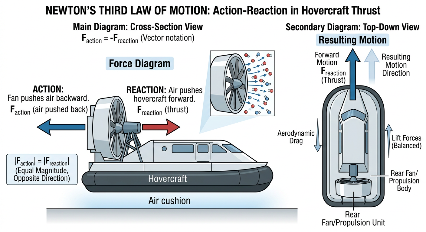
Newton's Third Law—for every action, there is an equal and opposite reaction—is the foundational principle governing thrust in all hovercraft. Unlike wheeled vehicles, which push against the ground via friction, or jet aircraft, which rely on atmospheric pressure differentials, a hovercraft generates forward motion by accelerating a mass of air rearward. The reaction to this acceleration is a forward force on the craft itself. Understanding the mechanics of this air acceleration and the resulting thrust is essential to sizing motors, fans, and power systems.
The principle is elegantly simple: a propeller (or axial fan) spins, its blades catch and accelerate a column of air from relative rest to some velocity v. By Newton's third law, the air exerts an equal and opposite force on the propeller—and thus on the entire craft—pushing it forward. The magnitude of this thrust depends on how much air mass is accelerated and to what final velocity.
Physical Principles and Momentum Theory
The quantitative relationship between thrust and air acceleration is derived from momentum conservation. Imagine a control volume surrounding the propeller and thrust fan:
Momentum Equation (1D):
F_thrust = ṁ · Δv
Where:
- F_thrust = thrust force (N)
- ṁ = mass flow rate of air through the fan (kg/s)
- Δv = change in velocity of the air (m/s), typically from 0 (relative to the vehicle) to the exhaust velocity
The mass flow rate can be expressed in terms of volumetric flow:
ṁ = ρ · Q
Where:
- ρ = air density (~1.2 kg/m³ at sea level)
- Q = volumetric flow rate (m³/s), often specified by fan manufacturers in CFM (cubic feet per minute)
Combining these:
F_thrust = ρ · Q · Δv
This relationship reveals a critical trade-off in propeller design. For a fixed power input, a team can achieve high thrust by accelerating a large volume of air to a modest velocity, or by accelerating a small volume of air to a very high veloc
…
3.2 Propeller vs. Impeller Design
Core Distinction
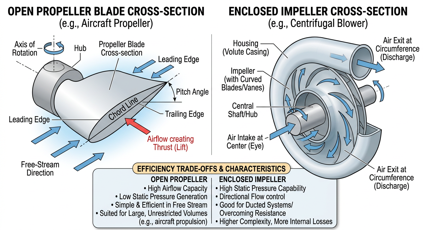
A hovercraft employs two fundamentally different types of fans, each optimized for a distinct functional role: a propeller (or axial fan) for thrust, and a centrifugal blower (or impeller) for lift. While both are centrifugal machines—they rotate to impart energy to a fluid—their designs, flow paths, and performance characteristics differ markedly. Selecting the correct fan type for each circuit is one of the most critical engineering decisions in hovercraft design.
Axial Fans (Propellers) for Thrust
An axial fan moves air in a direction parallel to the axis of rotation. The working principle is akin to a traditional aircraft propeller: blades mounted on a central hub sweep through air, imparting momentum in the axial direction. As air enters the fan from the front, it is accelerated rearward by blade pressure differentials (lift force on the blade surfaces), exiting at high velocity along the motor's centerline.
Key characteristics:
-
High volumetric flow rate (CFM): Axial fans are optimized for moving large volumes of air. A typical 10-inch BLDC-driven propeller operating at 8,000–12,000 RPM moves 200–500 CFM depending on blade pitch and motor power.
-
Low static pressure rise: The pressure difference from inlet to outlet is modest, typically 0.5–5 Pa for small propellers. This is adequate for thrust (accelerating air does not require overcoming large pressure barriers), but insufficient for the lift circuit, where air must be forced through a high-resistance skirt distribution system.
-
High efficiency at design point: For a given power input, an axial fan delivers more thrust than a centrifugal blower of similar size, because momentum is imparted over a large frontal area at a lower velocity. Efficiency drops sharply if operating far from the design point (very high back-pressure or starvation).
-
Simple construction: A propeller is a single-stage device—a hub, bla
3.3 Fan Efficiency & CFM vs. Static Pressure
Core Concepts: Flow Rate and Pressure
Every fan is characterized by two key performance metrics: volumetric flow rate (measured in cubic feet per minute, CFM, or m³/s) and static pressure (gauge pressure, measured in Pascals or inches of water column). These parameters define the operating point of a fan and, together, determine how effectively a fan performs its function in a hovercraft. Understanding the trade-off between CFM and static pressure, and how efficiency relates to both, is essential for optimizing vehicle performance and power utilization.
Volumetric Flow Rate (CFM):
Q = A · v
Where:
- Q = volumetric flow rate (m³/s)
- A = cross-sectional area of the airflow (m²)
- v = average velocity of the air (m/s)
CFM measures how much air volume passes through a point per unit time. For a propeller, this is the air accelerated rearward; for an impeller, this is the air entering the inlet. A fan's CFM output is typically specified at a reference condition: ambient pressure and free discharge (zero back-pressure).
Static Pressure (Ps):
Static pressure is the pressure exerted by a fluid in motion, excluding dynamic pressure (which arises from velocity). For a fan:
ΔP_static = P_outlet - P_inlet
In a hovercraft lift circuit, the lift fan must overcome two pressure drops:
- Friction and acceleration losses in the duct and distribution skirt
- Leakage losses as air bleeds from the cushion gap
If the total resistance is equivalent to 50 Pa of gauge pressure, the fan must generate at least 50 Pa to maintain operation. At lower pressures, the craft cannot levitate; at higher pressures, the cushion becomes over-pressurized, straining the skirt.
For a thrust propeller, static pressure is typically 1–5 Pa (the pressure drop across the propeller disk itself), because the exit nozzle is open to atmosphere.
The CFM–Pressure Trade-off and Fan Curves
Every fan has an intrinsic relationship between
…3.4 Propeller Shielding & Safety
Regulatory Framework
Science Olympiad rules are explicit: all rotating propellers and impeller blades must be shielded such that a 3/8-inch dowel cannot pass through or contact the blades. This rule exists to protect competitors, judges, and spectators from the high-speed impact of an unshielded propeller or impeller blade. A spinning propeller rotating at 8,000–12,000 RPM can impart severe laceration or crushing injury in milliseconds. Compliance with this safety rule is non-negotiable; failure to shield adequately can result in immediate disqualification, regardless of vehicle performance.
Beyond the rule, shielding serves a secondary engineering purpose: it influences airflow, affects motor cooling, and impacts vehicle mass and performance. An effective shield design must balance safety compliance, aerodynamic efficiency, thermal management, and structural simplicity.
Design Principles for Safety Guards
A propeller guard must:
-
Block direct contact: The guard must prevent a 3/8-inch (9.5 mm) dowel—the official test object—from touching any point on the blade. This typically means a mesh or perforated screen with openings no larger than 6 mm, or a solid cover with a minimum clearance of 12 mm (to account for measurement tolerance) between the guard and blade tips.
-
Allow adequate airflow: The guard should not severely restrict the volumetric flow rate (CFM) from the fan. Excessive flow restriction creates back-pressure, reducing fan output and increasing motor load. Empirical testing shows that a well-designed guard incurs only a 5–15% reduction in free-discharge CFM.
-
Minimize added mass: Every gram added to the motor/fan assembly increases vehicle inertia and total mass. For a hovering vehicle with tight mass constraints, a guard that adds more than 10–20 g represents a significant penalty.
-
Dissipate or manage heat: A guard that fully encloses a motor may trap heat, raising internal
3.5 Coandă Effect
Core Principle
The Coandă effect (also spelled Coanda effect, named after Romanian inventor Henri Coandă) is a fluid-dynamic phenomenon in which a moving stream of fluid tends to follow and remain attached to a nearby curved or flat surface, even as the surface deflects the flow away from its original path. In the context of a hovercraft, the Coandă effect is exploited to redirect high-velocity air from the lift fan toward the outer perimeter of the air cushion, improving the distribution of cushion pressure and enhancing craft stability and lift efficiency.
Unlike the Bernoulli effect (which reduces pressure in high-velocity flow), the Coandă effect is a momentum-based phenomenon—the flowing air entrains (drags along) fluid elements near the surface, creating a low-pressure region that pulls the flow toward the surface. As long as the surface curvature is gentle and the flow is turbulent or transitional (as is typical in hovercraft lift systems), the flow remains attached.
Physics of the Coandă Effect
Mechanism:
When a high-velocity jet of air exits a nozzle near a curved surface, the boundary layer (the thin region of fluid in contact with the surface) adheres to the surface due to viscous forces. Fluid elements at the surface are carried along the surface by skin friction; fluid elements just outside the boundary layer are entrained and follow suit. This entrainment creates a region of lower pressure adjacent to the surface, which draws the core jet toward the surface. The pressure gradient forces the flow to follow the curvature, even if the deflection angle is substantial (up to 45–60° for well-designed surfaces).
Mathematical description:
The pressure distribution in a Coandă flow can be approximated using the Coandă law:
δ/d = C · (L/d)^(-1/3)
Where:
- δ = thickness of the detached jet centerline (m)
- d = nozzle exit height or diameter (m)
- L = distance along the deflecting surface (m)
- C = empirical coefficie
3.6 Gyroscopic Effects & Torque Reaction
Core Phenomenon
A spinning propeller is a rotating rigid body with significant angular momentum. When a propeller rotates at high speed (e.g., 8,000–12,000 RPM), it possesses rotational inertia and angular momentum that create two related but distinct effects: gyroscopic precession and torque reaction (also called reaction torque or engine torque). Both effects can cause a hovercraft to rotate (yaw) unintentionally, degrading performance and complicating vehicle control. Understanding these effects and how to counteract them is essential for designing stable, predictable hovercraft.
Angular Momentum and the Gyroscope Principle
Angular momentum (L):
L = I · ω
Where:
- L = angular momentum (kg·m²/s)
- I = moment of inertia of the propeller (kg·m²)
- ω = angular velocity (rad/s)
For a propeller disk of mass m and radius r:
I_propeller ≈ (1/2) · m · r²
For a typical 10-inch (0.25 m diameter) propeller weighing 50 g (0.05 kg):
I ≈ (1/2) × 0.05 × (0.125)² ≈ 0.000391 kg·m²
At 10,000 RPM = 1047 rad/s:
L ≈ 0.000391 × 1047 ≈ 0.409 kg·m²/s
This angular momentum is a vector, directed along the propeller's axis of rotation (by the right-hand rule).
Gyroscopic Precession
Definition and mechanism:
Gyroscopic precession occurs when an external force (torque) is applied to a spinning gyroscope (in this case, the propeller). Rather than rotating about the axis of the applied torque, the gyroscope rotates about a different axis—perpendicular to both the spin axis and the applied torque axis.
Precession rate:
τ = dL/dt
Torque applied to the gyroscope causes the angular momentum vector to change direction. The rate of change is:
Ω_precession = τ / L
Where:
- Ω_precession = precession angular velocity (rad/s)
- τ = applied external torque (N·m)
- L = angular momentum of the spinning object
Example: A hovercraft in a turn:
Imagine a hovercraft with a single thrust propeller rotat
…❓ Practice Questions
No practice questions linked to this module yet.
🎬 Study Videos
🔗 Resources
-
Official Science Olympiad event page for Hovercraft (Division C). Contains event description, links to official rules, recommended resources, and preparation guidance.
-
Full 2026 Hovercraft event rules including scoring formulas (TS, DS, BS), construction and competition violation penalties, tiebreaker criteria, and prohibited components.
-
Foundational curriculum guide explaining what a hovercraft is and the physics of air cushion lift. Free educational material from the international school hovercraft project — ideal for Module 2 grounding.
-
Explains how increasing air pressure under the hovercraft skirt generates the lift force that raises the vehicle off the ground. Covers the relationship between fan air volume and cushion pressure.
-
Quantitative treatment of hovercraft lift: lift force = cushion pressure × skirt enclosed area. Includes formulas for air gap clearance and pressure calculations relevant to Module 2 physics.
-
NASA's Beginner's Guide to Aeronautics covering all three of Newton's Laws with applications to thrust and drag. Essential physics background for understanding hovercraft propulsion and motion.