Helicopter Anatomy & Key Components
Helicopter competition and construction topics for Module 2
📖 Overview
Helicopter competition and construction topics for Module 2
📚 Study Guide
2.1 Motor Stick (Body)
The Spine of the Machine
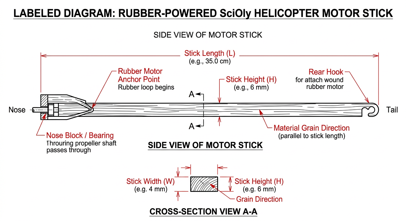
The motor stick — sometimes called the body, fuselage, or boom — is the single structural element that ties your entire helicopter together. It anchors both rotor assemblies, houses the rubber motor along its full length, and determines the overall balance point of the aircraft. Despite its apparent simplicity, the motor stick is the most consequential structural decision you will make during design. A poorly chosen stick introduces unnecessary mass, bends under torque loads, vibrates during flight, and shifts the center of gravity away from its optimal position.
Function and Structural Demands
The motor stick must perform three simultaneous structural roles:
- Axial tension/compression: The rubber motor pulls inward on both hooks when wound, generating significant axial load along the stick. A stick that cannot resist this compression will bow or snap.
- Torsional resistance: As the rubber unwinds, it exerts a reactive torque on the body. If the stick is too flexible torsionally, it will twist slightly during flight, misaligning the rotor shafts and degrading performance.
- Bending resistance: Aerodynamic forces from the rotors act perpendicular to the stick axis, especially during climb. The stick must resist bending to keep both rotor planes parallel and horizontal.
The ideal material therefore exhibits high specific stiffness — high Young's modulus E and shear modulus G relative to density ρ. The specific modulus E/ρ tells you stiffness gained per unit mass; maximizing it lets you build a stiff stick that doesn't penalize the weight budget.
Common Materials and Their Trade-offs
Balsa wood remains the most common choice for beginner and intermediate builders. Medium-grade balsa (density ~0.10–0.16 g/cm³, E ≈ 3–5 GPa along grain) is easily shaped, cheap, and available in consistent strip stock. A 3 mm × 3 mm × 300 mm balsa stick weighs roughly 0.14–0.22 g — competitive for mo
…
2.2 Rotors: Fixed vs. Free
Why Two Rotors Spin in Opposite Directions
A single spinning rotor generates lift — but it also generates torque. By Newton's third law, every torque the motor exerts on the rotor to spin it is matched by an equal and opposite reaction torque applied to the fuselage. In a conventional helicopter, a tail rotor counteracts this reaction. In a rubber-powered Science Olympiad helicopter, the elegant solution is to use two coaxial rotors that spin in opposite directions, canceling each other's torques and allowing the body to remain stationary while both rotors generate lift.
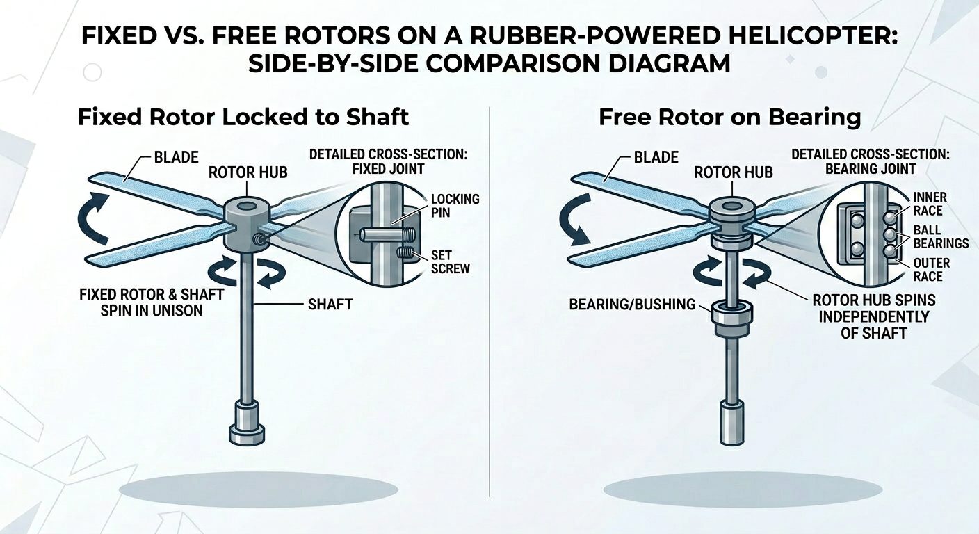
To achieve this counter-rotation from a single rubber motor, one rotor is fixed to the motor shaft (and spins with it) while the other rotates freely in the opposite direction due to the reaction torque transmitted through the body. This fixed/free distinction is the mechanical heart of the design.
The Fixed Rotor
The fixed rotor is permanently attached to the end of the rubber motor — typically to the wire motor hook or a small prop shaft that is glued directly to the motor stick. When the motor unwinds, the free end of the rubber (at the nose hook) drives this rotor. The rotor turns in the same direction as motor unwinding; if you wind clockwise (viewed from the front), the front rotor spins clockwise on unwind.
Because the fixed rotor is rigidly coupled to the motor, its pitch, diameter, and drag directly determine how quickly the rubber unwinds. A high-pitch, large-diameter fixed rotor extracts more energy per revolution but requires more torque to turn, causing faster motor depletion. A smaller, lower-pitch fixed rotor spins faster and depletes the motor more gradually but generates less thrust per revolution.
Key design parameter: The fixed rotor should be sized to extract energy from the motor at the same rate as the free rotor, balancing lift contribution from both ends of the aircraft. Imbalanced lift creates pitching moments and unstable fli
…
2.3 Rotor Spars & Ribs
Internal Skeleton of a Rotor Blade
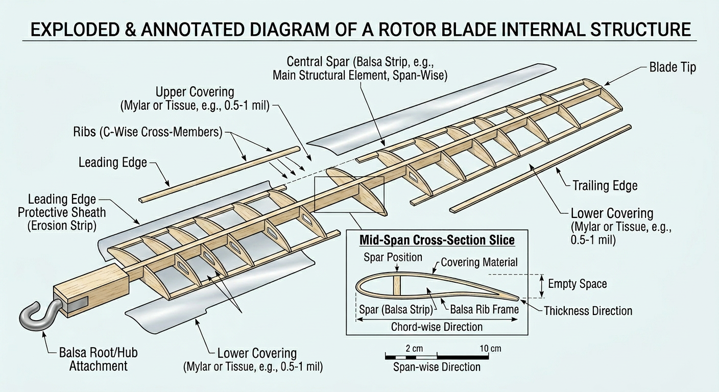
A rotor blade is not a solid piece of wood or plastic — it is an internally structured airfoil, much like the wing of a full-scale aircraft in miniature. The internal framework consists of two families of members: spars, which run lengthwise (spanwise) along the blade, and ribs, which run chordwise (from leading edge to trailing edge), maintaining the airfoil cross-section under aerodynamic load. Together, they form a lightweight skeleton that covering materials (tissue, Mylar, or none) are stretched over to create a lifting surface.
Understanding the mechanical role of each member — and how to optimize their geometry and material — separates builders who produce reliable, high-efficiency rotors from those who end up with warped, heavy, or structurally fragile blades.
Spars: The Primary Load Path
The spar is the backbone of the rotor blade. In flight, a rotor blade experiences bending loads (centrifugal force tries to flatten the blade; aerodynamic lift tries to deflect the tip upward) and torsional loads (aerodynamic center vs. elastic axis offset creates a pitching moment). The spar must resist both.
For a simple flat-plate rotor, a single leading-edge spar running the full span (from root to tip) is the standard design. Balsa strip stock (typically 1.5 mm × 3 mm or 2 mm × 2 mm) is most common. A second trailing-edge spar is sometimes added to improve torsional stiffness, but at a mass penalty. Carbon fiber strip (0.5 mm × 2 mm) is an elite-level upgrade that offers a 5–10× improvement in stiffness-to-weight ratio.
The bending stiffness of a spar scales with the second moment of area:
I = (b · h³) / 12
where b is the spar width and h is the height (dimension in the bending direction). This means doubling the spar height in the bending plane gives an 8× increase in bending stiffness. Orienting balsa strip so that the wider dimension is perpendicular to the rotor disc plane the
…
2.4 Prop/Rotor Shaft & Rotor Hanger
The Mechanical Interface Between Motor and Rotor
The rotor shaft and rotor hanger are among the smallest components on a rubber-powered helicopter — yet they are responsible for one of the most mechanically demanding tasks: transmitting torque from a twisted rubber strip to a spinning rotor blade assembly with minimal friction, precise alignment, and zero wobble. Failures in this assembly account for a disproportionate share of competition-day crashes. Understanding the geometry, materials, and fit tolerances of these parts is non-negotiable for high-performance builds.
Definitions: Shaft vs. Hanger
The terminology can vary between builders and event coaches, so let's establish precise definitions:
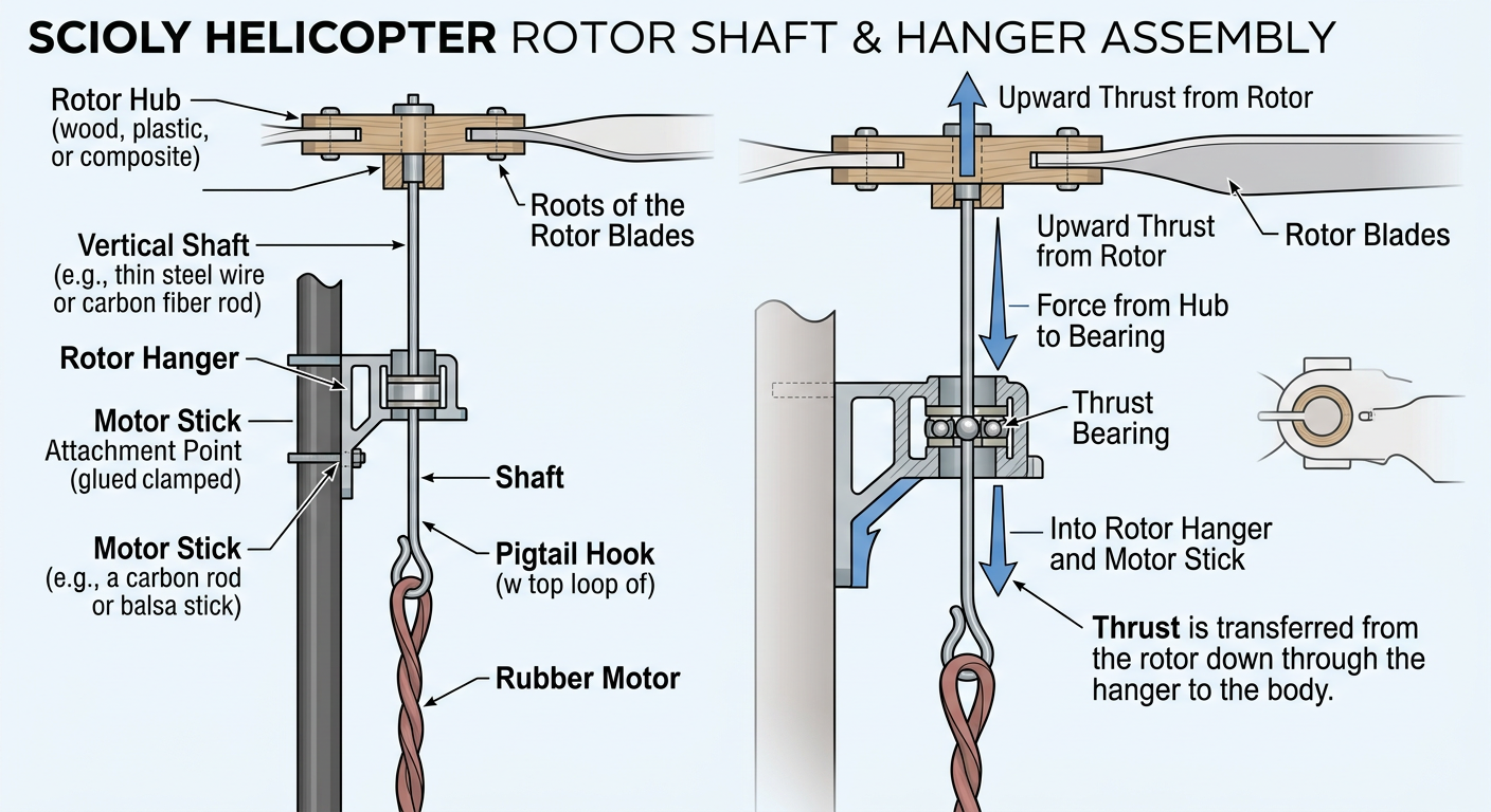
- Rotor shaft (prop shaft): The rigid wire or rod that extends from the end of the rubber motor, passes through or attaches to the motor stick, and provides the rotational axis for the free rotor. It is typically formed from wire (0.3–0.5 mm diameter steel or music wire) bent into a hook at the motor end and a loop or cross-pin at the rotor end.
- Rotor hanger: The bearing housing — typically a short tube of brass, aluminum, or plastic — through which the rotor shaft rotates. The hanger is fixed to the motor stick; the shaft rotates within it. The combination functions as a radial bearing, constraining the shaft's lateral position while allowing free rotation.
In some builder communities, the entire assembly (shaft + hanger + hub) is collectively called the "prop assembly" or "rotor bearing assembly."
Shaft Material and Diameter
Music wire (high-carbon spring steel, ASTM A228) is the standard material for rotor shafts. Its high yield strength (1000–2500 MPa depending on diameter) resists permanent bending under the lateral loads imposed by centrifugal rotor mass. Common diameters used in Science Olympiad helicopter builds are 0.3 mm, 0.4 mm, and 0.5 mm.
The tradeoff between diameter and performance:
- **0
2.5 Motor Hooks & O-Rings
Anchoring the Power Plant
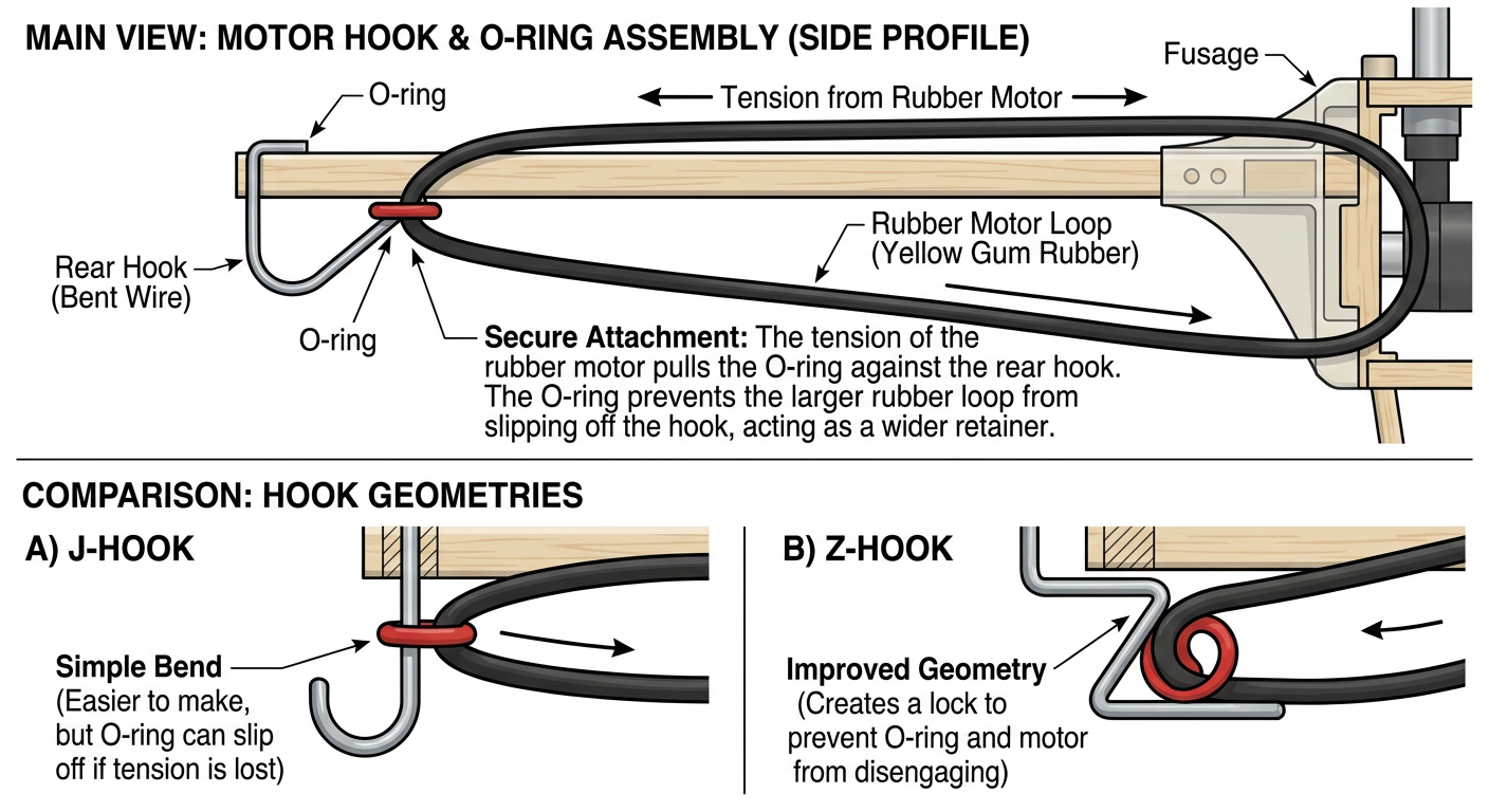
The rubber motor floats freely inside the motor stick, suspended only by two small wire hooks — one at each end of the body. These hooks are the sole mechanical interface between the energy source and the airframe. They must withstand the full axial tension of a tightly wound motor (which can exceed 1–2 N on a heavily wound strip), prevent the motor from slipping or rotating relative to the stick, and allow the motor to be easily removed for re-winding between flights. Small as they are, the design of these hooks and the O-rings that often accompany them has real performance consequences.
Anatomy of a Motor Hook
A motor hook is typically formed from 0.4–0.6 mm music wire or stainless steel wire bent into an L- or J-shape. The short arm of the L passes through or wraps around the motor stick, and the long arm forms a loop that the end of the rubber motor (knotted or looped) slips onto.
The critical geometric features are:
- Loop inner diameter: Should be 2–3 mm for typical rubber motor widths (1/8" = 3.2 mm wide). A loop that is too small forces the rubber knot to roll off under high tension; too large allows the knot to bounce and slip, delivering inconsistent torque.
- Mounting arm length: The arm that passes through or wraps the stick must be long enough to resist the rotational pull of the motor but short enough not to project and add aerodynamic drag or snag on anything.
- Loop orientation: The hook loop should be perpendicular to the stick axis so that axial motor tension is transferred cleanly to the stick. A hook loop that tilts even 15–20° introduces a lateral bending moment on the stick at the attachment point.
Rear Hook vs. Front Hook
The rear hook (at the winding end of the stick) takes the rubber motor loop that connects to the rubber motor directly. This is the end at which you apply the winder. The rear hook must resist both the axial pull and the rotational torqu
…
2.6 Measurement Box
The Design Envelope That Defines Everything
Before your helicopter ever leaves your hand, it must fit inside a rectangular volume — the Measurement Box — defined by the Science Olympiad rules. This single constraint is the design envelope that determines the maximum possible rotor diameter, the longest permissible motor stick, and the total volume available for your airframe. Understanding the Measurement Box is not an afterthought; it is the first constraint that every serious builder works from, because all other design choices flow downstream from it.
Current Dimensional Specifications
The Measurement Box dimensions may vary slightly by year and division; competitors should always verify against the current year's official rules. As of recent seasons, the box for Helicopter (Division B and C) has been specified as:
75 cm × 75 cm × 75 cm (a cube, approximately 29.5" × 29.5" × 29.5")
Some rule sets instead specify a rectangular prism with one elongated axis — for example, 45 cm × 45 cm × 60 cm — to accommodate longer, slimmer helicopter body designs. Always read the current year's event rules carefully. The box is typically provided at competition by the event supervisors and is made of wood, foam board, or PVC framing.
The helicopter must fit inside this box in flight configuration (rotors attached and in their flight position) before and after each flight, typically at impound or at the launch pad before each flight attempt. A helicopter that does not fit incurs a penalty or disqualification per the current rule set.
Geometric Implications for Rotor Diameter
The Measurement Box directly caps the rotor diameter. For a coaxial helicopter with both rotors at approximately the same diameter and mounted on the same vertical axis, the maximum rotor diameter is constrained by the shortest horizontal dimension of the box.
For a 75 cm cube, the theoretical maximum rotor diameter is 75 cm — but practical clearance requiremen
…2.7 Covering Materials
The Surface That Meets the Air
Once the rotor skeleton — spars, ribs, and leading/trailing edge strips — is complete, a builder faces a critical decision: what material, if any, to stretch over the frame to create the lifting surface? This choice directly determines the mass, drag, and lift-generating area of each rotor blade, and it propagates through every other performance variable. There is no universally optimal choice; the correct covering material depends on rotor geometry, pitch design, motor energy budget, and the competition environment. Understanding the physical properties of each option allows builders to make principled decisions rather than copying defaults.
Option 1: No Covering (Bare Frame / Open-Structure Rotors)
An open-frame rotor consists only of the structural members — spars and ribs — with no membrane stretched over the skeleton. This is the lightest possible configuration. For a 65 cm diameter two-blade rotor, removing the covering can save 0.2–0.5 g per rotor, which is significant on a 4–6 g helicopter.
The aerodynamic trade-off: an open-frame rotor generates significantly less lift per revolution because it has almost no continuous lifting surface — only the narrow chord of the structural members themselves produces aerodynamic force. The effective chord and thus the lift coefficient drop sharply. Open-frame rotors are only viable when rotor diameter is very large (low disk loading compensates for low blade area) or when the weight savings are critical enough to justify the aerodynamic penalty.
In practice, bare-frame rotors are rarely competitive at the national level for Science Olympiad Helicopter, where energy-efficient lift generation matters more than minimum rotor mass.
Option 2: Tissue Paper Covering
Japanese tissue (also called Esaki tissue or model aircraft tissue) is the traditional rotor covering material in rubber-powered aircraft. It is ultra-thin (typically 4–7 g/m²), provides a
…❓ Practice Questions
No practice questions linked to this module yet.
🎬 Study Videos
🔗 Resources
-
Two-page NFFS PDF giving a structured overview of helicopter anatomy, construction sequence, and what students and coaches need to know when starting the event.
-
Simplified step-by-step guide to rubber motor selection, winding procedure, and helicopter testing; covers the operational skills needed for Module 7 flight operations.
-
Template and explanation for recording flight data; covers what to log, how to analyze results, and how the flight log contributes to competition scoring (bonus points for a completed flight log).
-
Full kit building instructions for the 2026 Freedom Flight Science Olympiad helicopter; covers balsa selection, carbon fiber application, mylar covering, and assembly sequence in detail.
-
NASA technical paper analyzing airfoil performance at low Reynolds numbers — highly relevant since model helicopters operate at Re much lower than full-scale aircraft; supports advanced physics test component.
-
Official SOINC event page with rules, scoring criteria, links to construction and winding videos, and official resources. The authoritative source for current-year rule clarifications.