Rotor Design & Theory
Helicopter competition and construction topics for Module 3
📖 Overview
Helicopter competition and construction topics for Module 3
📚 Study Guide
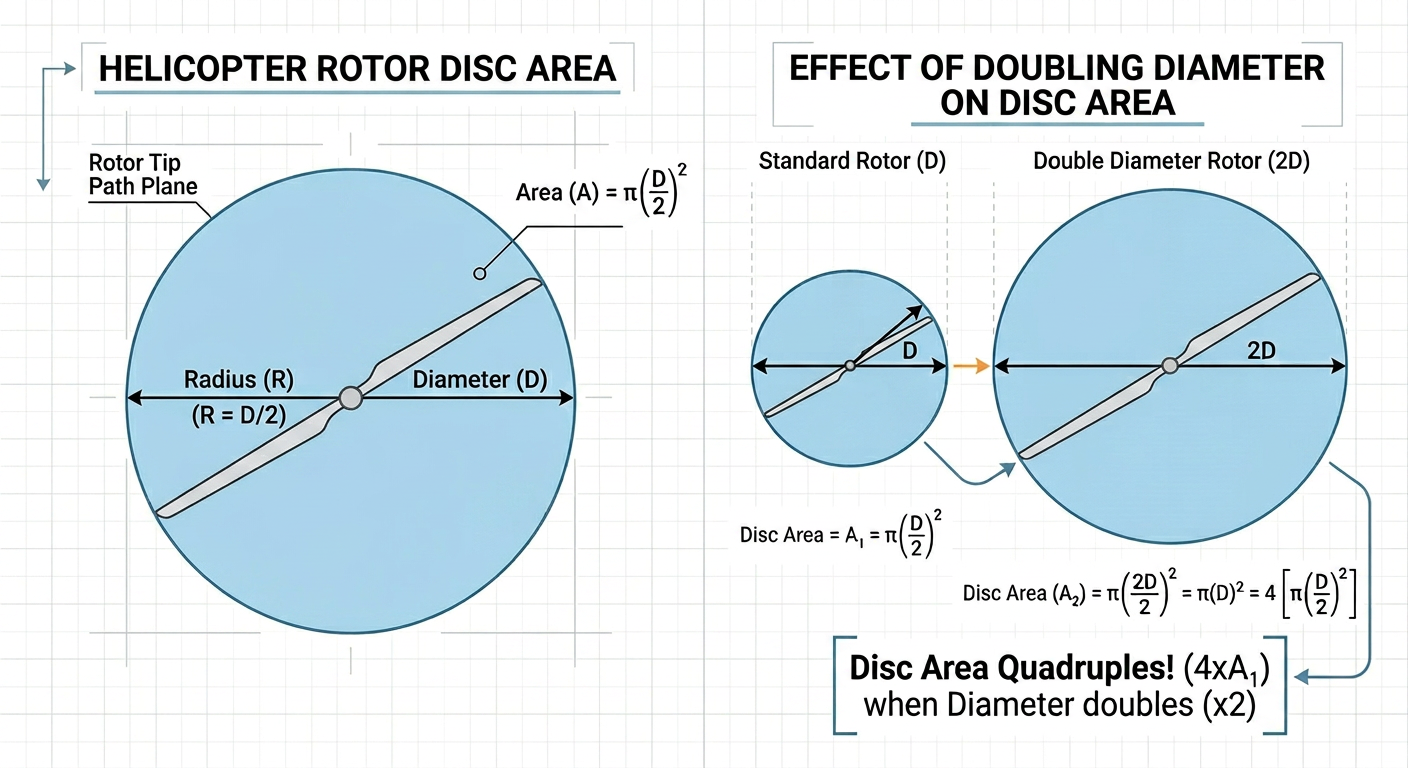
3.1 Rotor Diameter & Disc Area
Why Size Matters Above Everything Else
If you had to choose a single rotor parameter that most influences flight time, it would be diameter. A larger rotor sweeps a bigger disc of air each revolution, allowing the helicopter to generate the same amount of lift while accelerating air less aggressively — and that gentler acceleration is far more energy-efficient. This principle is not intuitive to beginners, who often assume that fast-spinning, small rotors must be more powerful. Actuator Disk Theory tells a different story.
Actuator Disk Theory: The Physics of Lift Efficiency
Actuator Disk Theory (ADT) treats the rotor as a thin, uniformly loaded disk that accelerates a column of air downward. The rotor imparts a momentum change to this air column, and by Newton's third law, the air column pushes the helicopter up. The key relationships are:
Thrust:
T = ṁ · Δv
Where ṁ is the mass flow rate of air through the disk and Δv is the induced velocity imparted to that air.
The mass flow rate through the disk is:
ṁ = ρ · A · v_i
Where:
- ρ = air density (~1.225 kg/m³ at sea level, standard conditions)
- A = disc area = π · R² (m²)
- v_i = induced velocity at the disk (m/s)
For hover, thrust equals weight (T = W), so:
W = 2 · ρ · A · v_i²
This gives us the induced velocity needed to hover:
v_i = √(W / (2 · ρ · A))
And the ideal (minimum) power required to hover is:
P_ideal = T · v_i = W · √(W / (2 · ρ · A)) = W^(3/2) / √(2 · ρ · A)
This final expression contains the most important design insight: ideal hover power scales as 1/√A. Double the disc area, and you need only 71% as much power to hover. Quadruple it, and you need only 50%.
Translating Disc Area to Rotor Diameter
Since A = π · R², rotor radius (and diameter) has a square-root effect on area but the area itself has a square-root effect on power. The net result: **ideal hover power scales inversely with diameter (P ∝
…
3.2 Blade Pitch & Angle of Attack
The Angle That Drives Everything
Blade pitch is the single most important tunable parameter on your completed rotor. Unlike diameter — fixed once the blades are cut — pitch can often be adjusted between flights by gently bending the blade root or adjusting the hub angle. Getting pitch right is the difference between a helicopter that climbs briskly and one that spins furiously but barely leaves the table.
Defining Pitch and Angle of Attack
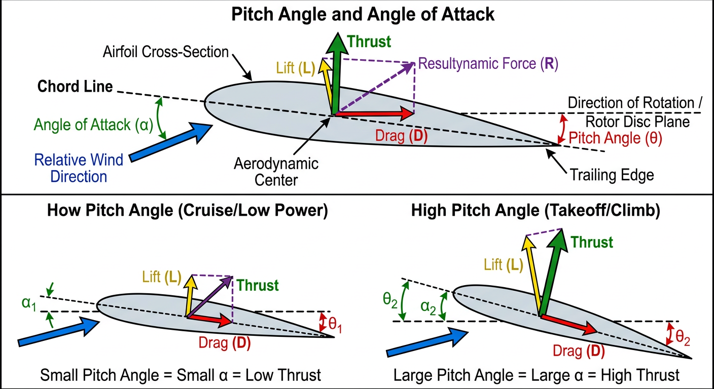
Geometric pitch (often called simply "blade pitch" or "collective pitch") is the angle between the chord line of the blade and the plane of rotation (the horizontal plane swept by the spinning rotor). It is measured in degrees. A blade lying perfectly flat in the plane of rotation has 0° pitch. A blade tilted so its leading edge is higher than its trailing edge has positive pitch.
Angle of attack (AoA) is the angle between the blade chord line and the local relative wind — the actual direction of airflow as seen by the blade in motion. Because the blade is both rotating (creating a tangential velocity component) and moving through descending-column air (the induced inflow), the local relative wind is not the same as the rotation plane. In hover, the relative wind comes slightly from below the rotation plane, so the effective AoA is slightly less than the geometric pitch:
AoA = θ_pitch − φ_inflow
Where φ_inflow (the inflow angle) = arctan(v_i / v_blade), with v_i the induced velocity and v_blade = Ω·r the blade velocity at radius r.
For a typical 300 mm rotor at 300 RPM with an induced velocity of ~0.3 m/s, a blade section at 75% span (r = 112 mm) has v_blade ≈ 3.5 m/s, giving φ_inflow ≈ 4.9°. If geometric pitch is 12°, the actual AoA is about 7.1° — already considerably lower than the set pitch.
Lift and Drag as Functions of AoA
At the blade section level, lift and drag are:
L = ½ · ρ · v² · c · C_L(α)
D = ½ · ρ · v² · c · C_D(α)
Where:
- c = cho
3.3 Number of Blades: 2 vs. 4
The 2026 Bonus Changes the Calculus
For many years, the optimal blade count for Science Olympiad helicopters was treated as a pure aerodynamics question. The 2026 rules change the framing: two-bladed rotors receive a 1.1× score multiplier. That single rule means that a two-bladed design which flies only 5% shorter than the equivalent four-bladed design will outscore it after the bonus is applied. Understanding the aerodynamic and structural tradeoffs — not just blindly choosing two blades — is essential for making this decision intelligently.
Blade Count and the Distribution of Disc Loading
For a rotor with N_b blades of chord c and radius R, the solidity ratio σ is defined as the fraction of the rotor disc actually covered by blade material:
σ = (N_b · c · R) / (π · R²) = (N_b · c) / (π · R)
Solidity is a key non-dimensional parameter in rotor aerodynamics. Higher solidity means more blade area to generate lift, but also more profile drag surface.
For two rotors of the same diameter generating the same total thrust:
- A 4-bladed rotor with chord c has σ₄ = 4c/(πR)
- A 2-bladed rotor with chord 2c (to keep the same total blade area) has σ₂ = 4c/(πR) — identical solidity
If we keep total blade area constant, blade count alone does not change the ideal induced power (which depends only on disc area and total thrust). The difference lies entirely in profile drag distribution across the blades.
Induced Drag Per Blade at Low Reynolds Number
At Science Olympiad scales, rotor tip speeds are low — typically 3–6 m/s — compared to full-scale helicopters (150–200 m/s). This places blade sections in the low Reynolds number regime (Re ~ 5,000–30,000), where aerodynamic efficiency is strongly Reynolds number-dependent.
The induced drag coefficient for a finite-span lifting surface scales as:
C_Di = C_L² / (π · e · AR)
Where e is the Oswald span efficiency and AR = R/c is the blade aspect ratio. A four-bladed ro
…3.4 Blade Profile & Camber
Flat Plates vs. Airfoils: Why Shape Matters
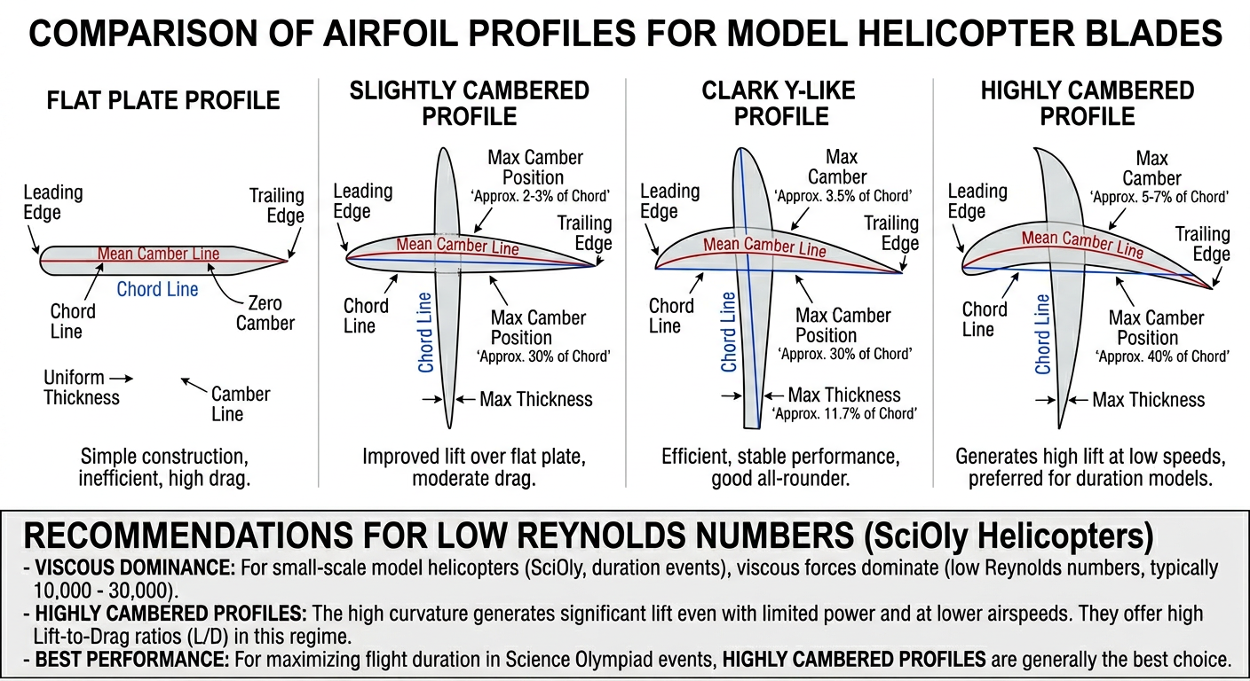
The simplest rotor blade is a flat strip of balsa — easy to cut, consistent in pitch, and light. Most beginner and intermediate builds use exactly this. However, a flat plate is aerodynamically inferior to a cambered airfoil section, particularly for lift generation. Understanding why — and when the added complexity is worth the effort — is the focus of this topic.
Thin Airfoil Theory: Camber and Lift
Classical thin airfoil theory (Joukowski, 1910; von Kármán and Trefftz, 1918) predicts that the lift coefficient of a cambered thin airfoil is:
C_L = 2π(α + 2·f/c)
Where:
- α = geometric angle of attack (radians)
- f = maximum camber (the maximum deviation of the mean camber line from the chord line, in meters)
- c = chord length (meters)
- f/c = camber ratio (dimensionless)
The term 2·f/c represents the "zero-lift" angle-of-attack offset: a cambered airfoil generates lift even at α = 0. A flat plate (f = 0) generates zero lift at α = 0 and must be pitched up to generate any lift at all. A cambered blade generates lift at lower geometric pitch, meaning it can operate at a smaller pitch angle for the same thrust — with potentially less profile drag.
For a modestly cambered balsa blade with f/c = 0.06 (6% camber), the zero-lift contribution is:
ΔC_L = 2π × 2 × 0.06 ≈ 0.75
This is substantial — equivalent to adding 0.75 to C_L at every angle of attack. For comparison, C_L at 5° pitch for a flat plate is approximately 2π × sin(5°) ≈ 0.55. A 6% cambered blade at 0° geometric pitch generates more lift than a flat plate at 5° pitch.
Practical Camber Methods for Balsa Blades
Adding camber to balsa requires controlled bending or carving:
- Steam or moisture bending: Lightly dampen one face of the balsa blade and clamp it over a curved form (a cylindrical dowel works well). As the moisture evaporates, the differential drying locks in curvature. This is
3.5 Coaxial vs. Tandem (Chinook) Configurations
Why Two Rotors at All?
A single-rotor helicopter requires a tail rotor to counteract the torque reaction of the main rotor. The tail rotor consumes power — roughly 10–15% of total shaft power in full-scale helicopters — without contributing to lift. For Science Olympiad rubber-powered helicopters, where every milliwatt of power is precious, eliminating the tail rotor and using a counter-rotating two-rotor system is nearly universal. Two primary layouts accomplish this: coaxial and tandem.
Coaxial Configuration
In a coaxial helicopter, both rotors share the same vertical axis, with one rotor above the other spinning in opposite directions. The upper rotor's torque is exactly cancelled by the lower rotor's torque, eliminating any net yaw tendency without a tail rotor.
Advantages:
- Compact footprint: the entire system fits within a circle equal to a single rotor diameter — important for the measurement box constraint
- Simple yaw control: speed differential between rotors produces yaw in full-scale systems (not directly relevant for S.O., but the counter-torque cancellation is elegant)
- Aerodynamically efficient: the lower rotor operates in the downwash of the upper rotor, which reduces its effective AoA. Careful pitch differential between upper and lower rotors can partially recover this loss
Disadvantages:
- The lower rotor operates in the downwash of the upper rotor, reducing its thrust contribution by approximately 10–20% compared to an isolated rotor generating the same power
- Shaft and bearing design must accommodate two concentric, counter-rotating shafts — mechanically complex for hand-built models
Upper vs. Lower Rotor Interaction:
In coaxial hover, the upper rotor accelerates air downward at velocity v_i,upper. The lower rotor encounters this pre-accelerated air, meaning it starts with a higher inflow velocity. By Actuator Disk Theory, additional acceleration of already-moving a
…3.6 Rotor Washout & Twist
The Spanwise Velocity Problem
A rotor blade is not a point — it extends from the hub (r ≈ 0) to the tip (r = R). At any given RPM Ω, the local velocity of each blade section varies linearly with radius:
v(r) = Ω · r
At the hub end (r → 0), v → 0. At the tip (r = R), v is at its maximum. For a rotor spinning at 300 RPM (Ω = 31.4 rad/s) with R = 0.15 m, the tip velocity is:
v_tip = 31.4 × 0.15 = 4.7 m/s
At 50% span (r = 0.075 m), v = 2.4 m/s. At 25% span, v = 1.2 m/s. This three-fold velocity variation from mid-span to tip is unavoidable — it is the geometry of rotation.
If the blade is built with constant (uniform) pitch, the angle of attack at each section varies dramatically. At low-radius sections where velocity is low, the effective AoA (geometric pitch minus inflow angle) is high — often beyond the stall angle for the blade section. At high-radius sections near the tip, the high velocity means a smaller inflow angle and a lower effective AoA. The result: the inner blade sections operate in stall while the outer sections are lightly loaded.
What Is Washout?
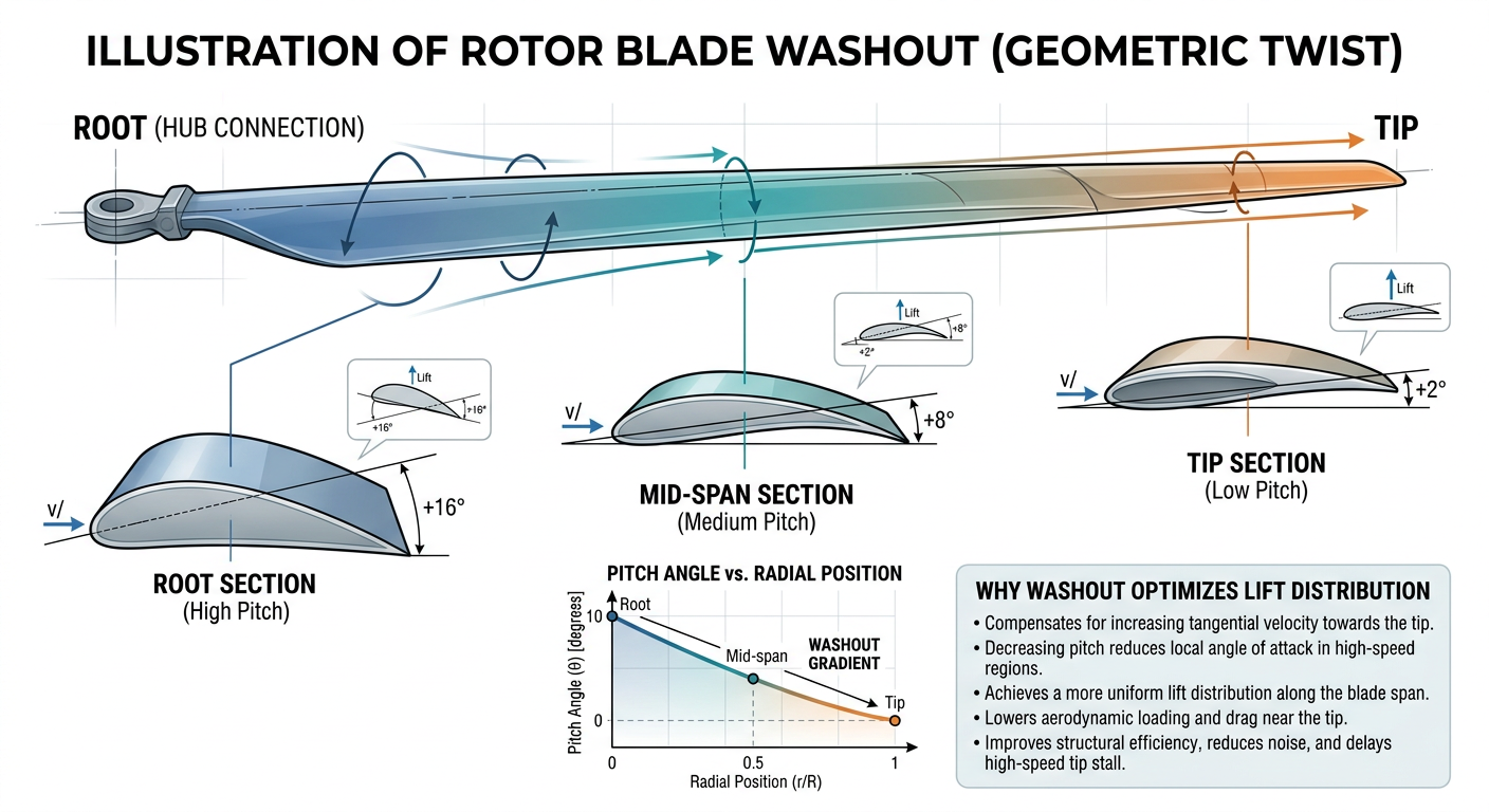
Washout is the intentional reduction of geometric blade pitch from root to tip — specifically, the root is set at a higher pitch angle than the tip. This counteracts the velocity gradient:
- At the root (low v): high pitch, but the inflow angle is also large, so AoA ≈ pitch − inflow ≈ moderate
- At the tip (high v): reduced pitch, but inflow angle is small, so AoA ≈ pitch − inflow ≈ also moderate
The goal is to equalize the effective angle of attack (and therefore the lift per unit span) across the entire blade — a condition called ideal (linear) twist.
The Ideal Twist Distribution
For a rotor hovering in an ideal (uniform inflow) condition, the blade pitch distribution that maximizes efficiency is:
θ(r) = θ_tip · (R / r)
This is called ideal twist: pitch varies inversely with radius. In practice, this distribution is difficult to build ex
…
3.7 Figure of Merit (Rotor Efficiency)
A Single Number for Rotor Quality
When comparing two rotors that generate the same thrust, how do you decide which is more efficient? The answer is Figure of Merit (FM) — a dimensionless ratio that compares the power a rotor actually consumes to the theoretical minimum power any rotor could use to generate the same thrust. It is the rotor designer's analog of the Carnot efficiency for heat engines: a ceiling that no real system can exceed, and a benchmark against which actual performance is measured.
Definition
FM = P_ideal / P_actual
Where:
- P_ideal = the minimum possible power to generate thrust T, from Actuator Disk Theory: P_ideal = T^(3/2) / √(2·ρ·A)
- P_actual = the power actually delivered to the rotor shaft (torque × angular velocity)
FM ranges from 0 to 1. A perfect rotor with no profile drag, no tip losses, and perfectly uniform disc loading would have FM = 1. Real full-scale helicopter rotors achieve FM of 0.70–0.80. Science Olympiad-scale rotors typically achieve FM of 0.25–0.50 — substantially lower, for reasons rooted in low Reynolds number physics.
Decomposing Actual Power
The actual power consumed by a rotor in hover can be broken into two components:
P_actual = P_induced + P_profile
Induced power (P_induced) is the power spent accelerating air downward to generate thrust. Even an ideal rotor must pay this cost. In practice, real rotors pay somewhat more than P_ideal because their inflow is non-uniform across the disc:
P_induced = κ · P_ideal
Where κ (kappa) is the induced power correction factor, typically 1.1–1.2, accounting for tip losses, non-uniform inflow, and wake swirl.
Profile power (P_profile) is the power spent overcoming aerodynamic drag on the blades as they sweep through the air. It depends on the blade drag coefficient C_D0, solidity σ, disc area A, and tip speed V_tip:
P_profile = ⅛ · σ · C_D0 · ρ · A · V_tip³
Rewriting in combined fo
…3.8 Blade Balancing & Tracking
The Hidden Performance Killer
A helicopter can have perfect rotor diameter, ideal blade pitch, beautiful cambered airfoils, and well-chosen motor — and still vibrate so severely that it loses 20–30% of potential flight time. The cause: unbalanced or mismatched blades. Vibration wastes energy (shaking the airframe rather than lifting it), stresses the structure, and destabilizes the rotor's flight path. Blade balancing and tracking are not finishing touches — they are fundamental requirements for competitive performance.
The Physics of Rotor Imbalance
A rotor with two opposing blades of slightly different mass generates a net centrifugal force that rotates with the rotor. If blade 1 has mass m₁ at center-of-mass radius r₁, and blade 2 has mass m₂ at center-of-mass radius r₂, the system is balanced only if:
m₁ · r₁ = m₂ · r₂
Any deviation from this condition creates a rotating centrifugal force F_imbalance:
F_imbalance = (m₁·r₁ − m₂·r₂) · Ω²
At 300 RPM (Ω = 31.4 rad/s), even an imbalance as small as 0.01 g·cm (1 mg offset at 10 cm radius) generates:
F = 0.01 × 10⁻³ kg × 0.1 m × (31.4)² = 0.001 × 986 × 10⁻³ ≈ 1 mN
This 1 mN oscillating force may seem small compared to the ~40–50 mN hover thrust, but because it is sinusoidal at rotor frequency, it excites structural resonances. If the fuselage natural frequency is near rotor frequency (common in lightly-built balsa structures), even small imbalance forces produce large-amplitude vibrations.
Mass Imbalance vs. Aerodynamic Imbalance
Two independent types of imbalance affect rotor performance:
Mass imbalance occurs when the two blades differ in total mass or in the spanwise location of their center of mass. The result is the rotating centrifugal force described above. This is corrected by static balancing.
Aerodynamic imbalance (also called pitch imbalance or aerodynamic asymmetry) occurs when the two blades have different effective pitch a
…❓ Practice Questions
No practice questions linked to this module yet.
🎬 Study Videos
🔗 Resources
-
Two-page NFFS PDF giving a structured overview of helicopter anatomy, construction sequence, and what students and coaches need to know when starting the event.
-
Simplified step-by-step guide to rubber motor selection, winding procedure, and helicopter testing; covers the operational skills needed for Module 7 flight operations.
-
Template and explanation for recording flight data; covers what to log, how to analyze results, and how the flight log contributes to competition scoring (bonus points for a completed flight log).
-
Full kit building instructions for the 2026 Freedom Flight Science Olympiad helicopter; covers balsa selection, carbon fiber application, mylar covering, and assembly sequence in detail.
-
NASA technical paper analyzing airfoil performance at low Reynolds numbers — highly relevant since model helicopters operate at Re much lower than full-scale aircraft; supports advanced physics test component.
-
Official SOINC event page with rules, scoring criteria, links to construction and winding videos, and official resources. The authoritative source for current-year rule clarifications.